


LCD LCD screen driver IC:
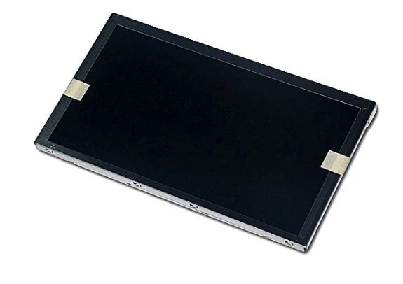
The LCD driver IC is the main part of the display imaging system. It integrates components such as resistors, regulators, comparators and power transistors, including LCD modules and display subsystems. It is responsible for driving the display and controlling the driving current. It is divided into static There are two methods of driving and dynamic driving.
Driver IC features:
Built-in 256khzrc oscillator, external 32.768khz crystal or 256khz frequency input, internal 32×4bit display. ram can choose 1/2 or 1/3 bias, and 1/2, 1/3 or 1/4. Terminal serial interface duty cycle LCD LCD screen has built-in lcd drive signal source, internal time reference frequency, can be commanded to control operation, buzzer drive signal frequency can be selected 2khz or 4khz. Data mode and command mode commands, with shutdown commands can be reduced Power consumption, r/w address automatically accumulates internal time base generator and wdt. Watchdog timer, 3 data storage mode time base or wdt overflow output, vlcd pin is used to adjust the operating voltage.
Driver IC:
(1) ram static display: The structure is 32×4 bits, which stores the displayed data. The content of ram is directly mapped to the content of the drive. The data in ram can be read, written and read—modify—write commands are accessed.
(2) System oscillator: cms1621 system clock is used to generate time base/wdt circuit clock, LCD drive clock and buzzer frequency. The clock can come from on-chip, oscillator (256khz), crystal oscillator (32.768khz) or an external 256khz clock set by s/w.
(3 Time base and watchdog timer: The time base generator is composed of an 8-level incremental counter, which is used to design and produce an accurate time base. The watchdog timer (wdt) consists of an 8-level time base generator and a It is composed of a 2-level incremental counter. It is used to stop the main controller or other subsystems in an abnormal state (unknown or undesired jump, execution error, etc.).
(4) The buzzer output provides a simple buzzer oscillator in cms1 621. The buzzer oscillator can provide the driving signals bz and bz for the buzzer to generate a simple buzzer. Execute tone4k and tone2k commands to generate two beep frequencies. Tone4k and tone2k commands set the beep frequencies to 4khz and 2khz respectively. The beep drive signal can be turned on or off by calling tone on or tone off.
(5) LCD LCD screen driver IC cms1621 is a 128 (32×4) dot matrix Icd driver, which can drive 1/2 or 1/3 bias, 2, 3 or 4 com-end LCD displays. This feature makes cms1621 is suitable for a variety of LCD displays.
(6) Command format: cms1621 can be set by s/w. There are two modes for setting cms1621 and transmitting LCD display data commands, namely command mode and data mode. The setting of cms1621 is called command mode, where id is 100, which is composed of system setting command, system frequency selection command, lcd structure command buzzer frequency selection command and operation command.
(7) The interface cms1621 has 4 lines that need to be interfaced. cs initializes the serial interface circuit and connects the communication terminal between the main controller and. When CS is 1, the data and commands between the main controller and cms1621 are prohibited and initialized.


